
John949
MYA Member
-
Joined
-
Last visited
Everything posted by John949
-
Shouldn't that be forward a bit? Weather helm is caused by the sail plan's centre of effort being behind the hydrodynamic centre so you need to move the sails forward to reduce the tendency to luff up. Or have it got it wrong? My own boat (not a 6 metre BTW) is driving me mad because it balances nicely when close hauled but develops vast amounts of weather helm on a reach and broaches at the drop of a hat. Any suggestions for a cure gratefully received.
-
Thanks John, I had forgotten about Rule 43. Any comments on the other two questions? Is yellow allowed to sail green past the mark? Does yellow lose her Rule 11 rights once green enters the zone?
-
There is an error that I found in the on-line forms in this area (which I have reported). The spreadsheet counts the number of heights you enter and checks that this matches the length of the foot. So, for example, if your foot length was 425mm there should be 9 entries - h0 to h8 at 0, 50,100 .... 350, 400. Unfortunately there is a bug in the spreadsheet that if one of the entered values is zero, then it ignores this value and counts one less height than you have entered. I don't know if this is your problem but try adding / removing entries until the error goes away and see whether it wants too many or too few entries. Or if you post your data I can check it for you. You may also notice that the graphs it draws of the sail profile look odd at the head. This is because it assumes that the head width is zero (why I don't know) so if your sail has a reasonable head width (my mainsail is 90mm) then the graph is not very helpful. I to have been entering my own data into the on-line forms and have many comments on the layout of the forms, the fact that huge parts of the final certificate are just guidance (and may be totally irrelevant to your particular sails), and the lack of any instructions / explanation on how to fill them in (even to the extent of which fields you have to enter and which are automatically generated). The fact that all the formulae are hidden doesn't help you understand what they do and hence resolve issues like this. If you want to see the formulae then is is pretty simple to unlock a sheet - you just take a copy of the spreadsheet and each sheet will then unlock without a password. Unlocking the whole workbook is a bit more complex but Google is your friend.
-
Is rule 18 actually relevant here? Isn't the situation covered by Rule 11 W/L and Rule 13 Tacking? How fast yellow is allowed to luff is governed by Rule 17. Even if she were the overtaking boat, Yellow's proper course is to round the mark if she can so green would still have to keep clear under Rule 11. Rule 18 would be relevant if they were leaving the mark to starboard, in which case yellow would have to give green mark room. I think we all agree green has to give yellow room, but if it's under Rule 18 then yellow has to bear away and round the mark "in a seamanlike fashion", if it's under rule 11 then yellow can sail on past the mark if he/she wanted to. I also struggle with what happens if yellow establishes the overlap inside the zone. Rule 18 says that yellow must give green mark room, but how do you give mark room to a boat on your outside? I'm pretty sure that the intention is that yellow loses her Rule 11 rights if she doesn't establish an overlap before green enters the zone - I just don't think the rule is very well written to convey that.
-
My personal view is that our whole measurement process could be simplified. At the moment every boat and its rigs are subject to quite a detailed measurement procedure which takes time and effort even before you add in the current hiatus concerning measurer's qualifications. All that tells you is that that boat and that rig measured on that day, it does not tell you that they will remain within the class rules for ever more. For example, boats tend to gain weight as they age and for a 10R this can easily put it over its original waterline length. There is also the issue of deliberate cheating - it's pretty easy to put new panel(s) in a sail while retaining the panel with the stamp and the signature. I'm not saying that such practices occur, I'm just trying to point out that, for a major championship, you can't rely on the original measurement and you have to conduct sample tests at least or possibly even completely re-measure the first few boats (like post race scrutineering in motor racing). Given that you need do this testing anyway, then do we need to measure every boat and every sail to the same degree if it is only going to be used for club racing? An alternative way forward might be to conduct a few simple checks on the hull and allow sails to be self certified by the maker (including home made sails) and then issue a certificate on this basis. If we kept the basic tests simple enough (e.g. use templates rather than rulers) then the training requirements for 'basic measurers' would be pretty low and a few more people might be willing to undergo it. Spot checks and sample measurements would then be carried out at major events by 'fully certified' measurers. Hopefully it would be self-policing as anyone getting repeatedly disqualified from major events would have some explaining to do to their customers and/or be obvious candidates for 'random' testing. This idea would need a bit of tweaking for each class e.g. classes with variable sail dimensions would probably need the sail maker to provides a 'certificate' with the actual dimensions and area on it to allow easy spot checking. 10R waterline measurement is always going to be tricky but I don't think anyone could claim that you need to go on an RYA sail measuring course to do it!
-
Brad, Ah I think I understand what you are saying at last. I've just emptied the tank otherwise I'd have a try. Richard, sorry for the thread hijack, I promise to stop now, except.... how have you put the WL marks on your boat if you haven't made the A rig yet? Setting up a 10R is a bit iterative as you have to sort of guess a waterline, make an oversize rig, weight it, re-do the WL, trim down the rig and so on. In practice one iteration is usually enough but you do need to know the weight of the heaviest rig (almost always the A) before you can finally set the marks. I shall be interested to hear how it goes against other 10Rs. I suspect it might go well until you have to change down to the B rig i.e. give up your sail area advantage but suffer with a shorter WL. The Bentley's party piece is to be able to carry more sail area than most in a given wind strength, of course the wind has to be strong enough for everyone else to need to reduce sail area below the Bentley's maximum. It's on these days that I remember why I like sailing it so much. Makes up for all the drifting match days when I get embarrassed by well sailed IOMs!
-
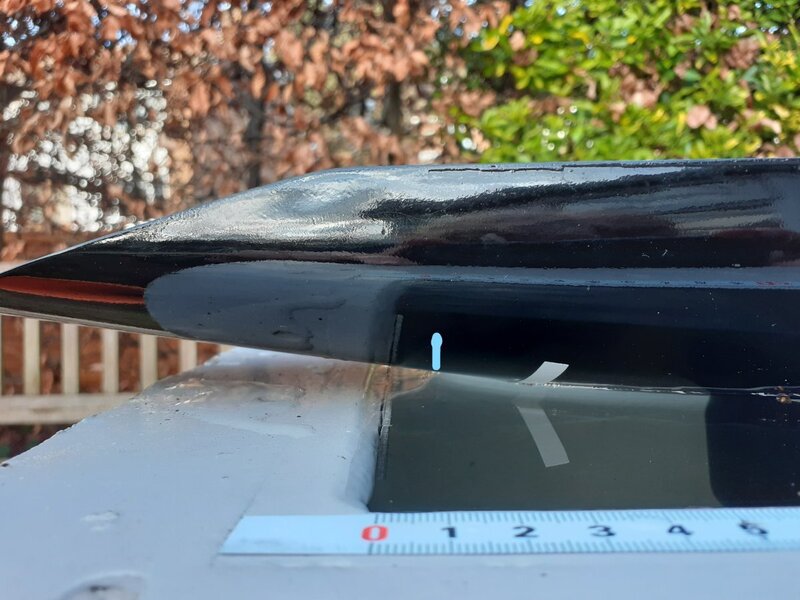
Unfortunately this picture doesn't show the meniscus as well as I'd hoped. It does show how bad my paint job is though! The blue line marks where the meniscus ends (if you look closely you can see the reflection of the bushes behind ends at this point because the water surface is no longer horizontal). What I was trying to show is just how far apart the waterline mark and the meniscus are - it's around 25mm! Brad, I don't understand your comment about 'ignoring the meniscus'. If you look under the boat with a mirror, all you can see is the edge of the meniscus. The sketch below reflects my understanding of the physics of surface tension. I agree you can see where the meniscus attaches to the hull and where it stops distorting the water surface, but neither of these is where the hull intersects the waterplane. In other words, you can see Point A and Point B but you can't see Point C

-
Brad, I assume you've seen this: https://www.sailsetc2.com/downloads/waterline end checking device 10R.pdf It shows that Mr Bantock thinks the waterline is measured where the waterplane intersects the hull, not where the meniscus touches the hull. When Roger Stollery checked my Bentley for me he also used a device that used the same principle. If you measure by sighting the meniscus you will get a value some 5-25mm longer than if you use the Bantock / Stollery method (depending on the hull shape) so it is significant. Unfortunately the rules don't help because they use the term ''waterline ending" without defining what this means. One of the difficulties with the Bantock / Stollery method is that you can't set the 'gauge' by sight, you have to 'feel' when the boat touches it - hence my original comment about it being difficult and error prone. One of the reasons swing rigs aren't as universal on 10Rs as they are on Marbleheads is because the 10R rules require the B rig sails to fit within the profile of the A rig sails. As swing rigs need to use a tall narrow jib, this severely compromises you if you want to use a conventional B rig, as ideally you would want to use a much bigger jib for the B rig (as Marbleheads do). Some 10Rs use a B swing rig but I'm not convinced this is a great idea. In my view this rule is unnecessarily restrictive and is one of many I would change if I ruled the world. The current rules require you to re-measure the boat and get a new certificate if you want to change the profile of the sails but keep the area the same, surely it is only necessary to measure the new sails and confirm that they do not exceed the area quoted on the original certificate?
-
Of course a well sailed boat can beat a badly sailed boat but hydrodynamics still applies. If you accept the well known maximum hull speed formula (for displacement mode) then the Bentley should be just over 5% faster at it's ultimate hull speed (when upright of course). If we assume equal displacements, one would expect the drag curves for the two boats to cross over at some point towards their maximum speed. The POE would be expected to have a lower drag at low speed, because of it's smaller wetted area but it's wave making drag will rise faster due to the shorter waterline. The overhangs on 10Rs are intended to increase the waterline length when heeled so it gets a bit more complicated but having a longer waterline to start with is generally beneficial. My comment about measurement accuracy is to do with the waterline length. The overhangs of a 10R (particularly at the stern) make a very small angle to the water surface so that if you are 1mm out in height you will be about 5mm out in length. Now add in the meniscus problem and I estimate you could easily be 10-15mm out. Incidentally I haven't found a definitive statement on how to handle the meniscus effect in the rules. I just know the Messrs Bantock and Stollery both say that you should try to eliminate the meniscus effect when measuring the waterline. I believe there is a more accurate way for boats that have been designed using a CAD modelling system and that is to produce a graph of waterline length v displacement from the model. One then only needs to weigh the boat to determine its waterline (and verify that the hull is built to the model.) I found it very difficult to get repeatable results when checking my Bentley so in the end I took a range of measurements at different displacements and then curve fitted a graph to the results so I can determine the waterline length from the weight. My worst point was indeed about 15mm off a fair curve between the other points.
-
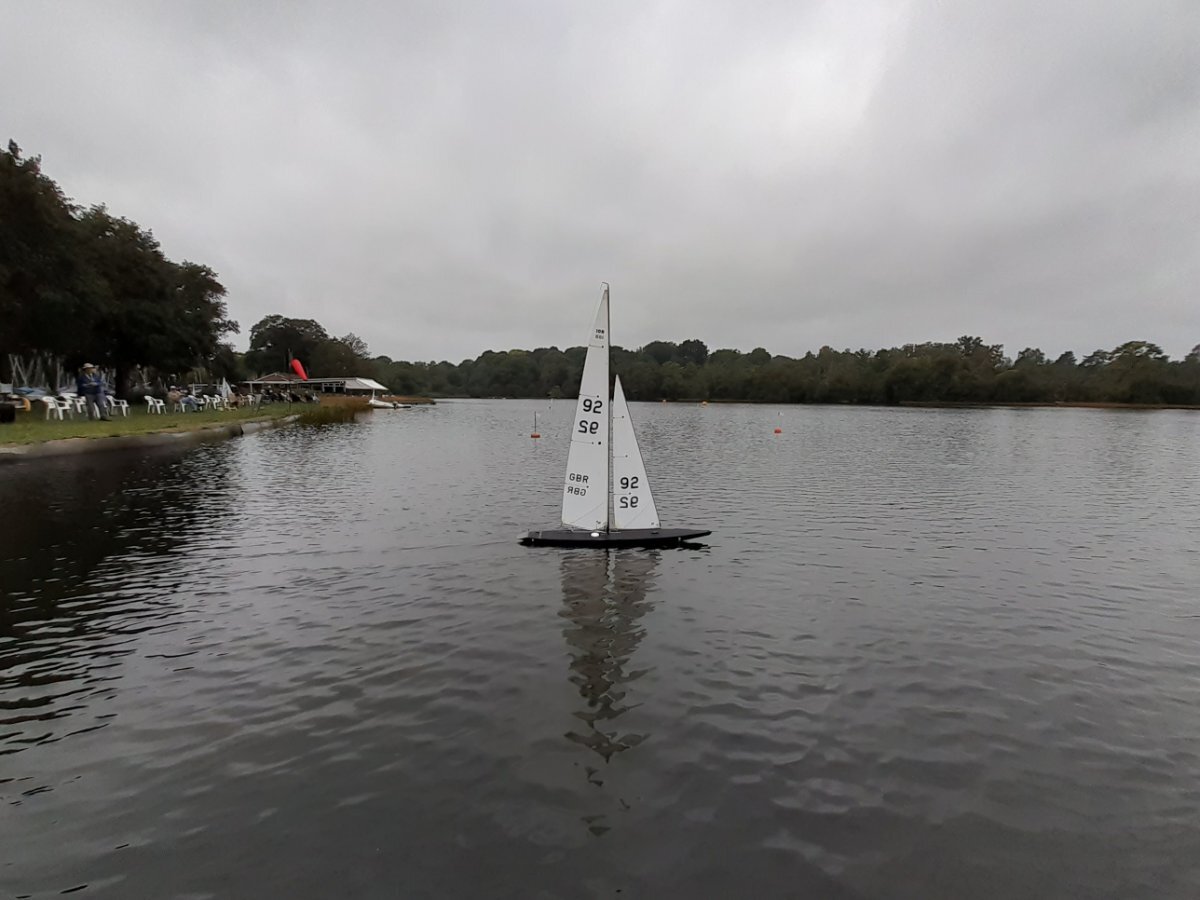
For comparison, a picture of the same sails on my Bentley. I think this highlights the major problem with the 10R class. Those sails are the maximum allowed for the Bentley's 1344mm waterline whereas the Pieces of Eight can have a significantly larger area. In winds under about 7kts I don't fancy the Bentley's chances but over 10kts there is only likely to be one winner. 10R's are lovely boats to sail and very fast but you sort of need a different one for every wind strength if you want to race seriously. Also probably best not to get me started on how hard it is to measure the damn things accurately.

-
The other thing to watch out for with older winches is the BEC voltage. Some of the early ones had a 5V 1 amp BEC, which is a bit marginal for a lot of rudder servos. The later ones are 6V 3amp. To find out simply measure the voltage on the plug that goes into the receiver. If you have a 5V one then you could use an external UBEC (I do) like this: https://www.ebay.co.uk/itm/254604123135?hash=item3b47969bff:g:ap0AAOSwGKRbN0kN You wire the UBEC direct to the battery and the output plugs into the receiver, but you must cut the red wire from the winch to the receiver (do this in a servo extension lead if you don't want to butcher your winch).
-
It's possibly cheaper here if you want a large amount (they also do end of rolls etc) https://www.profabrics.co.uk/products/adhesive-dacron?variant=5940860675
-
I think you mean 'gung ho', which has an interesting etymology: https://en.wikipedia.org/wiki/Gung_ho
-
There are two common types of cf tube. Pultruded and roll wrapped. Pultruded has the fibres orientated along the axis and is far stiffer in bending making it ideal for masts. The drawback is that it is fairly weak in the other directions and very easy to split if you try and force another tube into it or don't reinforce the ends. You could sleeve it but commercial grade tube is not precisely made and pultruded tubes don't usually fit inside one another easily. If you want to sleeve it then you could use a roll wrapped tube as you only want to stabilise the outer tube, not add any more stiffness. My limited experience is that roll wrapped tube is more likely to fit inside. It also has a thicker resin coating and so can be sanded / turned down more before the fibres break through. Your best bet however is to buy a new tube. Pultruded tube can be had for little more than roll wrapped but you must use external reinforcement on the outer tube of a joint and internal reinforcement at the bottom of the mast. You can get reasonably priced tube here: https://www.bucks-composites.com/products/carbon-fibre-pultruded-hollow-round-tube-1-metre-long The Sailsetc web-site has some good instructions and sizes for making masts. https://www.sailsetc2.com/downloads/RP15E.pdf The hardest part of making masts is getting the tubes to telescope nicely for the joins. I use a lathe to turn down the inner tube but you can do it be careful sanding, If you are going to risk doing it by drilling the outer tube you must reinforce it first.
-
Unlike a court of law, there is no onus on the protester (cf the plaintiff) to prove their case. The protest committee are required to review all the evidence presented and decide which is the more credible argument. See this link. https://www.racingrulesofsailing.org/manuals/1?section_id=12 Don't forget that negative testimony can be used as evidence. If n people (who were supposedly watching out for contact) didn't see anything then this would support a claim that there was no contact.
-
In theory all angles should be measured relative to the drawing baseline (the line at the top of the plan used to align the sections on your building board). This may or may not be parallel to the waterline. Again theoretically positive angles are clockwise (remember ACTS from your O level geometry). Having said that 'cant' usually refers to a sideways lean (as in illegal canting keels). The correct term for a fore / aft angle would be rake (as in mast rake). I agree that one would expect the keel to point up at the bow end slightly. This is because a force on the sails causes a bow down rotation of the boat (particularly in a gust) and so pointing the keel up reduces the drag a bit as the boat accelerates.
-
Class Registrar contact details are via the members area / officer contacts. 10R is Richard Uttley, M is Roy Stevens.
-
The 10 Rater and Marblehead sails look to have their full registration numbers on (i.e. 4 figures). If so the relevant class registrar (you can find their names and emails on this site) should be able to tell you something about them. Have you looked inside the hulls as it is normal for the registration number to be marked inside them on older boats.
-
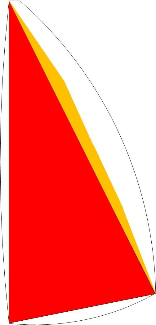
We all know that a Marblehead has a maximum sail area of 516100 mm2. Well it does and it doesn’t. It is true that the ‘certified’ sail area of a Marblehead is 516100 mm2 but, thanks to the rather arcane way in which the sail area is measured, the actual plan projected area is about 40% bigger than the quoted figure (assuming I’ve got my maths right). To put it another way, if you were to measure a set of Marblehead sails using the 10R rules, then the answer you would get would be about 722500 mm2 (which goes some way to explaining why 10Rs don’t beat Ms as easily as you might first think they should). The attached sketch explains why. For a mainsail (jibs are similar), the red area is measured as a triangle defined by the length of the luff and the perpendicular foot length (A and B in the measurement rules). If the cross-widths exceed a given limit then the orange area is also measured, however the white areas are always ‘free’ and account for a significant area of the sail. Does this matter? Again the answer is yes and no. If the certified area was always the same proportion of the actual area then it wouldn’t really matter, however a quick look at the measurement rules suggests strongly that this isn’t going to be the case and two sails with the same certified area could have different actual sail areas. To para-phrase George Orwell, ‘All Marblehead sails are equal but some are more equal than others’. By remembering my ‘O’ level trigonometry (that dates me!) I’ve managed to calculate a pretty good approximation of the actual sail area for a given set of measurements (i.e. A,B, X,Y & Z for a mainsail). It uses 8 triangles and three sectors in a spreadsheet with 70 columns so I won’t detail it here, I’ll just summarise the results. There are three basic parameters you can alter when designing a Marblehead sail, namely the length of the luff, the X,Y & Z dimensions and the height of the clew relative to the foot. The foot length would then be determined by your choice of the other parameters. Taking each of these parameters in turn. Luff Length The luff length has a fairly strong effect of the ratio of actual area to certified area, the longer the luff the greater the actual sail area. According to my calculations, a sail with a luff length of 1700mm has about 5% less actual sail area than a sail with a luff length 0f 2120mm (for the same certified area of course). For mainsails this isn’t a major concern as aerodynamic considerations would push you towards the longest luff anyway (a higher aspect ratio sail can produce the same amount of lift for less induced drag), however it does suggest that tall narrow jibs might have a small advantage over shorter wider ones. An interesting side effect occurs with reduced rigs. For example, if you wanted to create a B rig with a 10% reduction in actual sail are and a Luff length of 1700mm then you should only reduce the certified area by 5%. Clew Height The rules take no account of clew height and most swing rigs are made with the clew higher than the foot to try to prevent it hitting the water surface. Unfortunately raising the clew does incur a penalty in actual sail area. I calculate that having the clew 80mm higher than the foot incurs a penalty of about 1%. Not huge but just about significant. X,Y,Z Dimensions These measurements are what started this whole analysis off. They are often referred to as penalty areas, implying that you have to suffer a reduction in sail area if you use them. As I couldn’t see how the formula was derived (I’ve since learned it is based on Simpson’s Rule) I decided to try to calculate the effect for myself. The motivation being that (to my mind at least), modern Marblehead sails are too narrow in the upper part of the sail and one would like to make a sail that has a largish Z dimension, but does this cost you sail area and what should you make the X & Y dimensions? The answer is that, although I have a few problems with it, (see the thread on this subject) the formula in the rules is surprisingly accurate for reasonable values of X, Y & Z : less than 0.5% even in the worst case. For a typical max luff mainsail, there seems to be a peak at X = Y = Z = 16mm but it is only 0.04% above X = Y = Z = 0. Having Y greater than X & Z incurs a small penalty of 0.5% but you probably wouldn’t want a sail this shape anyway. My advice would be to make the sail the shape you want and not worry about the X, Y & Z dimensions. Caveats There are a couple of major caveats to my conclusions. Firstly, I could easily have got the maths wrong. It’s quite a tortuous calculation. Secondly, I’m only talking about maximising the plan area not aerodynamic efficiency. Just because a sail is slightly bigger it doesn’t mean the boat will go faster. I realise this sort of analysis is not for everyone but I thought the conclusions were interesting enough to post. If anyone wants more detail then I’m happy to give it. Conclusion I've never been a fan of the way Marblehead sails are measured as I believe it is error prone and doesn't measure the actual area. I think I've now proved that it is also unfair in relation to certain sail shapes. I would much prefer to use a method similar to the 10R rules as this would be much closer to the real area and allow much more freedom in sail shape. In my view laying a sail over a grid and measuring along the grid lines is much more accurate than trying to find equidistant points and then judging the minimum distance between it and the luff. This would however be a rather radical change and would also involve our American cousins calling it a 50/1120, so I can't see that happening anytime soon.

-
Thanks for that. Hadn't thought of Simpson's rule. There are a couple of approximations in the application here though. Firstly the quarter widths do not divide the luff into equal parts, in fact the widths of the 'steps' are dependent upon the value of X,Y & Z themselves. Graham's sketch seems to acknowledge this as they are not drawn on the 'step' lines. Secondly, the relationship between the luff length and leech length changes if the height of the clew varies. Typically conventional rigs have the tack and clew at the same height i.e. the boom is horizontal. Swing rigs tend to have the clew higher than the tack: to reduce the risk of it hitting the water. By using the luff rather than the leech, sails with a high clew attract a higher penalty than those with a parallel foot (because the leech length is reduced but the luff length isn't). I've been doing some calculations to estimate the actual sail area of a Marblehead (as opposed to the certified area). I'll publish the conclusions in a separate thread but (assuming I've done the sums right) the X, Y & Z values are pretty fair (less than 1% difference for reasonable values), but raising the clew 80mm gives a reduction of nearly 2% in real sail area for the same certified area.
-
Thanks but that's not really what I'm asking. It's easy enough to work out the effect of X, Y & Z on the certified sail area via the formula. What I'm trying to understand is how the formula was obtained in the first place because it doesn't appear to relate to the actual geometry of the additional area (well not that I can see anyway).
-
From what was posted previously, I understood that Pieces of Eight was a very radical design i.e. it was special design for use in very light airs as it had a very short waterline length and hence a large sail area. I also think that it a had a mast height which would now be illegal on a new boat. Whether you think this is a good basis for a new boat is your decision. You might be better of adapting a current design to chined construction. You could use two chines and produce a cross between an Enterprise and a modern 10R. Eat you heart out Dr Frankenstein.
-
The formula used to calculate the 'excess area' is A * (2X + Y + 2Z)/6. Does anyone know how this formula is derived? It's actually quite hard to work out the precise effect of the X,Y & Z dimensions on the sail area so I wonder if this is just a simple empirical formula that seems to work fairly well.
-
You could but I wouldn't. Ripstop is used for spinnakers because they have to be scunched up and generally mis-handled. Ripstop is a bit stretchy and not entirely windproof. Mylar makes a much better sail but you have to look after it and not crease it.
-
I can't give you precise details as I don't have this transmitter but I can give you some ideas to research. I don't know about 3 positions on the throttle but most helicopter settings have 2 using something called an 'idle up' switch. This is for setting higher idle speed when using a collective pitch helicopter. You should be able to program this to give a 'less sheeted in' position when the switch is operated. Another (possibly better) way, which will also give you the rudder function, is to use another (unused) channel that is operated by a three position swtich (flap?). If you then use one of the mixers to mix say 5% flap into throttle (or rudder) the switch will then give you -5, 0, +5 on the channel you are mixing into. (if you get the directions right). There are basically two models for using all the swtiches on knobs on a transmitter. 1) Each switch and knob is permanently associated with a function e.g. the flap switch alters the output of the flap servo. You then use the mixers and built in functions (e.g. V tail) to arrange for the switch / stick to affect other outputs. Most simple transmitters work this way. 2) Multiplex and some other transmitters are more flexible in that, for each output channel, you can specify any number of switches / sticks that will affect the output and in what way. You can spot these transmitters as the switches will be labelled things like 'two position switch' or 'three position switch' rather than 'idle up' or 'flap swtich' What they do depends upon how you program the transmitter.